
The following is based on a research paper I came across titled ABENICS: Active Ball Joint Mechanism With Three-DoF Based on Spherical Gear Meshings. A video description of the mechanism can be found in this YouTube video and it helpfully shows how the gears are designed and mesh together.
The paper describes a three degrees of freedom (3-DoF) ball joint mechanism with a really unique drivetrain, and it inspired me to build my own using 3D printed parts.
Overview
The design process took about one and a half months and is printed in PLA. The main mechanism is comprised of two highly specialized gears – the cross-spherical (CS) gear and the monopole (MP) gear. Together, as the YouTube video shows much better than I can describe here, these gears enable rotation, coupling, and sliding motion. Each monopole gear is driven by a pinion which is in turn driven by an internal worm gear.
The CS gear is contained within a housing. The remaining three gears of the drivetrain are mounted on a carrier that can rotate with respect to this housing. This way, the entire carrier and meshing CS gear can rotate in relation to the main housing, or if the carrier is held static, the internal worm gear can drive the pinion and MP gear to turn the CS gear in a second axis.
When fully assembled, the mechanism contains a single CS gear driven by two MP gears and their associated drivetrains.
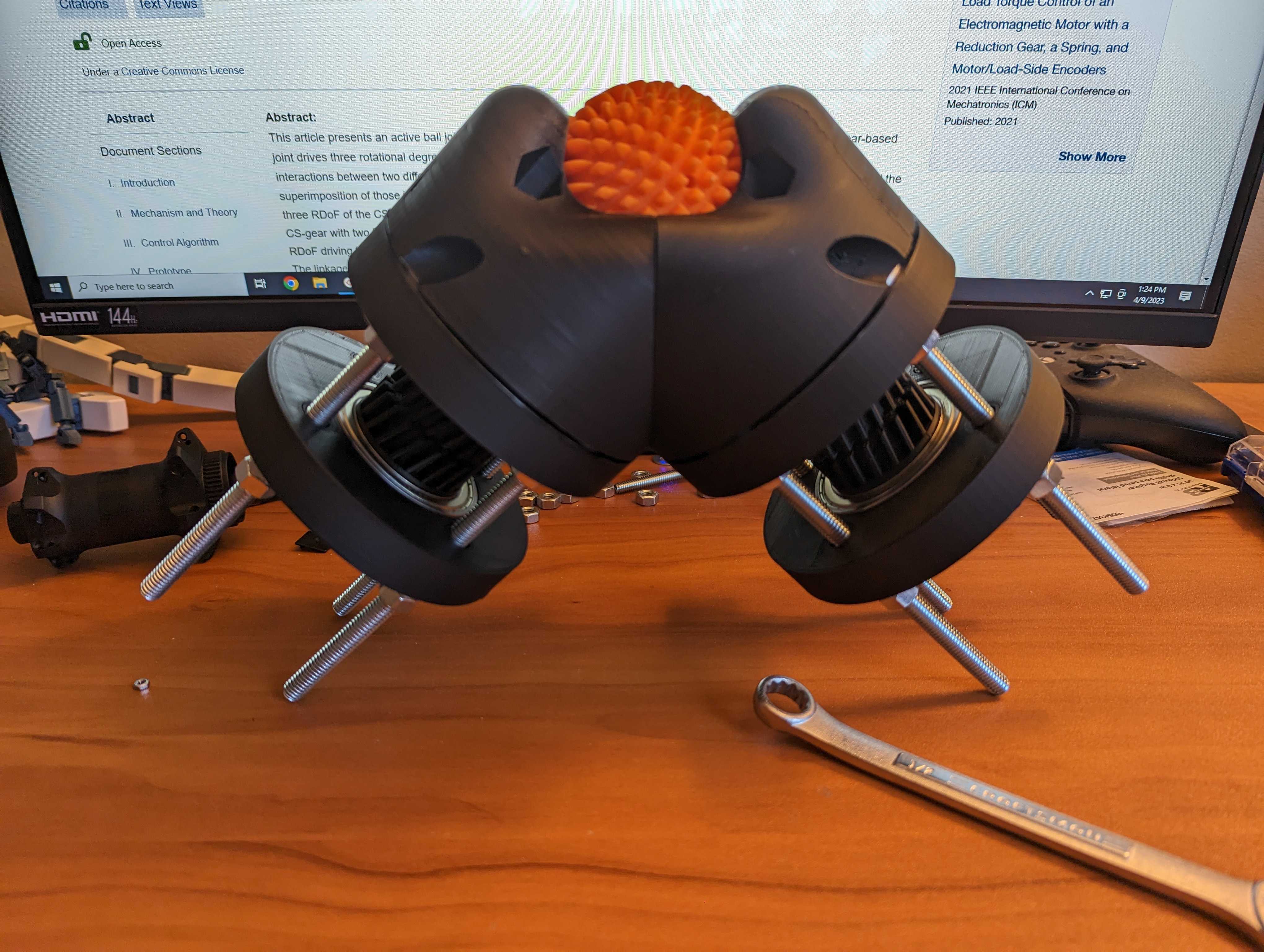
Examples
The full motion of this prototype can be seen below:
It is easier to visualize the full gear train if we section along the midplane of the assembly. In this view, we have full access to each gear in the drivetrain (from left to right):
- CS gear (output)
- MP gear
- Differential pinion
- Internal worm gear
The second gear behind the internal worm gear is affixed to the gear carrier and rotates the entire carrier wth respect to the main housing.
Exploded view of the parts:
Problems Encountered
Design Complexity
The most difficult part to design was definitely the MP gear. The YouTube video describes how this hobbing of the MP gear would normally take place.
I essentially recreated this process by creating a single spherical gear, meshing it with a solid cylinder, and rotated the cylinder with respect to the spherical gear in 6 degree increments. At each increment, the cylinder is rotated about the second axis and the impression of the spherical gear is subtracted from the cylinder.
This was repeated 30 times to achieve 1/2 of a monopole gear, and then mirrored for the complete gear. The combination of 6 degree increments and 30 total increments gives 180 degrees of rotation about the spherical gear and has reasonable dimensional accuracy, especially when 3D printed. Some rough edges can be seen in the 3D model but are too small to visualize in the finished part.
The process likely could have been scripted for simplicity, but my skills in Fusion360 were not quite up to this task.
Material Choice
PLA is really not the correct material for this application for two main reasons: (1) it can’t easily be sanded and (2) it has relatively high friction, which has implications specifically around the internal worm gear that drives the differential pinion. This caused quite a bit of problems with excessive difficulty turning the internal worm gear, which is the main input for rotational motion for the CS gear.
I spent quite a bit of time here hand-finishing this part to make sure the tolerances between it and the pinion were appropriate.
Layer Orientation
Layer orientation is a problem for the gear carrier. Because it serves many purposes, including providing mounting and rotational axes for most gears in the drivetrain as well as functioning as a major rotational axis itself, care needed to be taken to ensure good structural integrity of the part.
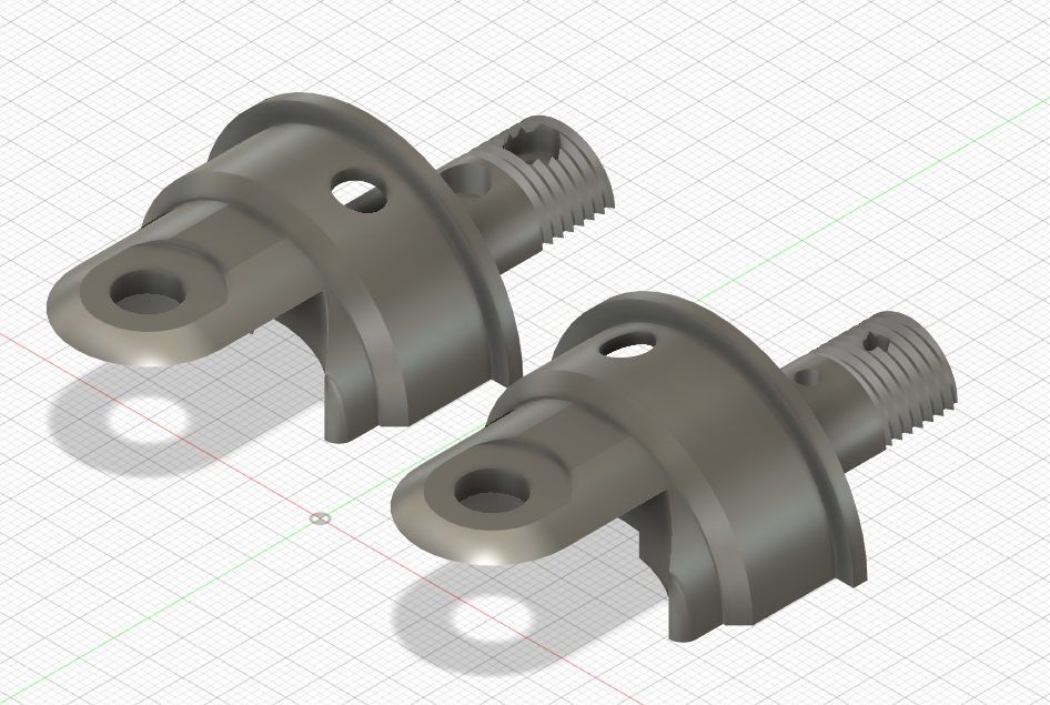
This part in early prototypes was printed in the orientation you see below.
However, as time went on and torque was applied to the part, I ended up shearing it in half at the shoulder right above the threads. This shoulder serves as a stop for the bearing which is mounted in the internal worm gear, and the threads are a temporary assembly helper for the helical gear that drives rotation of the entire carrier, until it can be compressed by the beefy 6908 bearings in their two housing plates.
To mitigate this issue, I split the part in half so that the layer lines were in a more favorable orientation. This traded dimensional accuracy at the threads for increased strength once fully assembled.
The small holes here were originally intended to be bolted together with M2.5 standoff screws and nuts, but once assembled I realized this will be compressed by an M8 bolt, 2 separate bearings, a pin for the pinion, and the threaded helical gear at the bottom, and so additional fixation is not needed.
Bill of Materials
The full guide to print and assemble this yourself is available here.
- PLA
- 8x 5/16”-18 by 5” hex bolts
- 28x 5/16”-18 hex nuts
- 4 go to the housing clamp screws
- 24x 5/16” washers
- 2x M8 cap screw
- MP gear mounting
- 2x M8 nut
- 4x 6908Z bearing
- main bearings
- 4x 608-2RS bearing
- MP gear bearings
- 2x 6202-2RS bearing
- internal worm bearings
- 4x 5/16”-8 by 3” button head screws
- main housing clamp screws
What’s Next?
Well, as you may have noticed, the research paper and associated video include four stepper motors to drive the motion of this ball joint. You may have also noticed that my prototype is missing these motors. This is a planned future enhancement, but given that I have spent almost two months working on this project as is, I plan to take a short break from it for the time being.
There are also some enhancements that I can improve on aside from the motors – backlash between the MP gear and pinion is extremely noticeable, either by transferring the backlash to the CS gear or especially in the internal worm gear due to its low gear ratio. Any backlash here means that a significant portion of the internal worm’s movement is “dead” until all the backlash is taken up.
That’s all for now. Thanks for reading!